Thursday, October 25, 2018

Indian road Congress

The Indian Roads Congress ( IRC ) was established in 1934 with the following objectives : 

  • To promote and encourage the science and practice of road building and maintenance. 
  • To provide a forum for expression of collective opinion of its members on matters affecting roads .
  • To promote the use of standard specifications and practices .
  • To advise regarding education , experiment and research connected with road.
  • To hold periodic meetings to discuss technical questions regarding road 
  • To suggest legislation for the development , improvement And protection of roads 
  • To suggest improved method of administration , planning, design, operation, use and maintenance of roads.
  • To establish, furnish and maintain libraries and museums for furthering the science of road making 

Tuesday, October 23, 2018

5 Different Types of Traditional Water Harvesting System in India

1. Rajasthan-Based Paar:

Paar was a harvesting practice used in the desert areas of Rajasthan. This involved collecting rainwater from the catchment to let it percolate into the soil. The water in the soil was then accessed by masonry construction of dugs (kuis) in the storage area. The kuis are about 5 m to 12 m deep.

2. Talaab:

These have been popular since the days of the kings. Talaabs are reservoirs—natural (as in Bundelkhand) or man-made (as in Udaipur). These reservoirs were used to meet irrigation and drinking water requirements. These constructions lasted only as long as the monsoon. Post-monsoon, the beds of these water bodies were cultivated with rice.

3. Saza kuva:

These wells were initiated on a partnership basis. With multiple users, these saza kuvas were primarily used for irrigation. A group of farmers usually had one made amongst themselves.

4. Johad:

ADVERTISEMENTS:These are earthen check dams that were meant to collect rainwater. Because of their earthen nature, water percolated easily into these systems. They resulted in tremendous rise of the groundwater levels.

5. Pat:

The pats of the Jhabua district of Madhya Pradesh are irrigation panels. These irrigation panels are fed using water that is diverted from fast moving hill streams.

Monday, October 22, 2018

BAR BENDING SCHEDULE FOR A SLAB

Bar Bending Schedule
Just like any other schedules, bar bending schedule is most important part of any project.
It helps in doing reconciliation of steel and controlling the wastage at site.
If bar bending schedule (BBS) is not prepared at site, then contractor and its workmen tend to cut and and bend bars without quantifying it and leads to more wastage due to over doing it.


I have created a Bar bending Schedule format in excel sheet, which can be used for followings;
Taking approval from Client or Engineer In-charge - Its a Certificate which allow workmen to do work accordingly.
Ordering the required reinforcement steel Quantity.
Issuing Steel bars to contractor as per BBS and avoiding overdoing and wastage.
Reconciliation of done work and identifying the issues in cutting and bending of steel.
It does a great help to fitter to do cutting and bending as all dimensions and cutting length already provided to them in BBS.
It increases productivity of reinforcement workmen and hence reduce the delays in construction activities.
enclosed herewith a sample of bar-bending schedule for the slab


FLOW NET

Before studying a flow net, the following terms need be clearly understood.


  1. Flow line - the line followed by percolating water through a saturated soil mass under laminar flow conditions, is called flow line .
  2. Equipotential line - the line joining the points of equal hydraulic potentials , is called an equipotential line.
  3. Flow net - the flow net work formed by a system of flow lines and equipotential lines . Is called flow net . A flow net is a pictorial representation of the pattern of flow and the dissipation of hydraulic head causing the flow in soil.
  4. Flow channel - The portion of a flow net bounded by two adjacent flow lines, is called flow channel.
  5. Field - The section of a flow channel located between two adjacent equipotential lines, is called a field 


FUNDAMENTAL CHARACTERISTICS OF A FLOW NET 


  • Flow lines and equipotential lines in a flow net intersect at right angles 
  • All fields formed by equipotential lines and flow lines are approximate squares. 
  • Same quantity of flow occurs through each flow channel 
  • Same potential drop occurs between any two successive equipotential lines 
  • The smaller the dimension of a field , greater is the hydraulic gradient and also velocity of flow .
  • In homogeneous soils, the shape of curves is either clliptical or parabolic. 

Sunday, October 21, 2018

What it is Hydrogen?


The branch of physical geography which deals with the origin, distribution, and properties of water of the earth surface is called hydrology.

Engineering hydrology deals with the field of hydrology which is mainly concerned with the wind and operation of engineering projects for the control and use of water . Indeed , the engineer makes use of hydrology as agriculturists , foresters, etc . do

The Hydrological cycle

Water goes on changing from one state to another in a cyclic order . This cycle is visualised at beginning with the evaporation of water from the oceans and lakes. The resulting vapoura are transported by the wind and under proper conditions, these vapours get condensed to form clouds which contribute to the precipitation . The precipitation which falls upon the land is disposed of in several ways as discussed below:

(1) the greater part is temporarily retained in the soil on which it falls and is ultimately returned to the atmosphere either by evaporation or by transpiration by the plants.

(2) A partion of water finds its way over and through the surface soil to stream channels 

(3) A partion of the water penetrates farther into the ground and becomes a parts of the earth's ground water supply.

Uses of hydrology

A study of hydrology ise useful for the following
  • For proper design and operation of hydraulic structures 
  • For ascertaining flood flows expected at a spillway , or at a highway culvert or in a city drainage system 
  • For ascertaining reservoir capacity to ensure adequate water for irrigation or municipal water supply during draughts 
  • For ascertaining the effect of reservoirs , levees and other control works in flood flow in a stream

Wednesday, October 17, 2018

Capacity of a highway

Before we discuss the capacity of a road pavement , the following terms may be clearly understood

  1. Traffic valume - the number of vehicles moaving in a specified direction on a roadway that pass a given point during a specified unit of time , is called traffic volume 
  2. Traffic density - the number of vehicles occupying a unit length of a roadway at a given instant, is called traffic density . It usually expressed as vehicles per kilometre 
  3. Traffic capacity - the maximum number of vehicles in a roadway that can pass a given point in unit time, is called traffic valume 
  4. Basic capacity - the maximum of passengers cars that can pass a given point on a roadway during one hour under the most ideal road and traffic conditions , is called basic capacity . It is something called theoretical capacity 
  5. Practical capacity - the maximum no of vehicles that can pass a given point on a roadway during one hour without imposing any restriction to the driver's freedom for driving the vehicles, under prevailing roadway and traffic conditions , is called practical capacity . It is some times called design capacity.


Masonry Dams

The structures that are constructed across drainages ( natural or artificial ) to retain water to the required height , are known as dams. The dams which are wholly constructed with stones , are called masonry dames
The following forces generally act on a dam section
1- weight of masonry acting downward
2- pressure of water acting horizontal
To avoid tension in masonry , it is ensured that the resultant of the forces on the dam section , lies within the middle third of the section
While analysing dam section , one should always consider a unit length of the dam .
Now consider the trapezoidal dam section of unit length
Let w= density of water retained
        h= height of water retained
        W = total weight of the masonry acting at its C-G
Water pressure P= 1/2 wh2 acting at h/3 form the base

The resultant R of the force P and W intersect the base at E . To locate E, take the moments of P and W about E. The resultant R may be considered to be equivalent to horizontal through P and vertical force W . The horizontal force does not affect the stresses at the base. The stresses which are developed at the base are, therefore, only due to load W and acts with an eccentricity ,

The maximum stress at the base is at the outer edge away from the water face and minimum stress will be at the edge near the water face

Spacing of rivets according to IS 800-1962

Following limitations are recommended:

  1. The distance between center of adjacent rivets should not be less then 2.5 times the diameter of rivet hole
  2. The distance between the centres of two adjacent rivets ( including tacking rivets ) joining the members both in conpresscom or in tension should not exceed 32t or 300 mm which ever is less , where t is the thickness of the cover plate 
  3. The diadista between the centres of two adjy rivets in the direction of stress shall not exceed 16 t or 200mm whichever is less in tension and 12 t or 200 mm whichever is less in compression

Monday, October 15, 2018

Advantages and Disadvantages of water Bound Macadam


  • Advantages - water Bound Macadam is superior in quality because the materials are carefully graded and the resulting mass is almost voidless compacted mass. The interlocking of aggregates particles imparts adequate strength of the materials selected for filling the voids . These ensure non entry of the plastic mstermat of the sub grade into the voids .


  • Disadvantages- the stone pieces used in water bound macadam road are keyed together by means of sand and clay and no other cementing material  is used . The bending effects of sand and clay depends upon the pressure of moisture. When the first moving vehicle passes over a W. B. M. Road, the slurry of sand and clay is sucked out by the pneumatic wheel types , the stone pieces get disturbed and finally road surface is disintegrated . Due to this factor , the w.B.M. roads are not suitable for fast moving vehicles with wheel types . These roads are only suitable for slow moving iron wheeled traffic such as tonges , bullocks carts etc, constant use of road by iron wheels , the road matal gets crushed . Considering these important factors , it may be inferred that a w.b.m. road survives only for a short time
A water bound macadam is less costlier as compared to bituminous base course. 

Classification of premix bituminous wearing surfaces

In premix method, the aggregate and the binder are premixed prior to placing and spreading the Mix over the pavement structure.
It mens that every individual aggregate particle receives uniform thickness of the binder film before it is placed . In primix mermet in construction increased stability is achieved because aggregate gradation may be carefully selected to given a dense mass possessing minimum voids.

In the case of grouted macadam , the binder has to reach the full or half aggregate layer by penetrating through the open voids between the aggregate particle. That is why In this construction, more quantity of bitumen is required to fill voids which are deliberately left in the pavement structure to enable the bitumenous binder to penetrate to the lowest layers of stones

The premix bituminous wearing surfaces are classified as under

  1. Bitumen bound macadam 
  2. Bitumen carpet 
  3. Bitumen concrete 
  4. Sheet asphalt
  5. Mastic asphalt

Sunday, October 14, 2018

Method of construction of W.B.M. Road

Water bound macadam roads are constructed through the following stages as detailed below : 


  1. Preparation of sub-grade - sub grade is provided by digging up the sub soil and the level of the sub - grade is decided by subtracting the total thickness of the pavement from the finished level of the road pavement . Form the finished level of the road pavement . The sub grade is throughly compacted by rollers weighing 8 tonnes by during rolling must be made up to and brought to the grade as required.  In rocky regions the sub grade are not rolled whearas in region of clay soils, a layer to natural sand moorum or gravel , is provided over sub grade and is duly-packed.
  2. Preparation of sub-base - on the well compacted subgrade , spread 10 to 20 cm size boulders or broken stones , or over burnt bricks in layer of 15 cm thickness and total width of the sub base to be kept 60 cm wider then the pavement width , projecting 30 cm on each sides . The sub base should be compacted by a roller to provide an even surface 
  3. Preparation of base - on the prepared sub- base or directly on sub grade, as the case may be, the specified materials of the base course is spread and proper grade, thickness and cross sections maintenaned as per design shown on the supplied drawings
  4. Preparation of wearing course - this course may be laid in one or two layers according to the total designed thickness and the thickness of each layer should not exceed 10 cm . This component being very important, the following steps may be taken systematically
      (1) check the defective portions of the newly laid                   base course i.e. soling and rectify them
       (2) provided either bricks on end edging or                         earthen kerbs strong enough to prevent the new road material form spreading outward and also to       l retain water used in consolidation of the wearing   ourse .

Monday, October 8, 2018

Method of Estimation of building works

The estimation of the quantities of various items of a building such as earth work in excavation, concrete in foundation , bricks work in foundation and plinth, brick work in super - structure, etc may be made by the following methods :
1 . Centre line method
2 . Long and short wall method


  1. Centre line method: 
In this method , the centre line length of walls in a building is multiplied by the breadth and depth of the respective item to get the total quantity of the item in case of partition or veranded walls joining with the main walls , the centre line is reduced by half of the breadth of the layer of the main wall at the same laver.                                                            Suitability: this method is especially suited for estimating the circular , hexagonal , octagonal, etc. Shaped buildings 

  2. Long and short wall method. 


In this method , the longer walles are generally treated as long walls and the shorter or partition walls as short Wallas . The long walls are measured out to out i.e. center to center  length and half projection on one side and half projection on the other side . The short walls are measured in to in i.e. center to center length minus half projection one side and half projection on the other side .
Suitability : this method is mostly used irrespective of veriable sections of walls 

DEFECTS OF BRICKS

  • 1. Over - burning of bricks 
  • If the bricks are overburnt, a soft molten mass is produced and the bricks losses their shape . Such Bricks are not used for construction works.

2 . Under - burning of bricks

  • When brick are not burnt property, the clay is not softened because of insufficient heat and the pores are not closed .
  • This results in higher degree of water absorption and less compressive strength 
  • Such bricks are not recommended for construction works 
3. Bloating 
  • This defect is observed as spongy swollen mass over the surface of burned bricks. 
  • It is caused due to the presence of excess carbonaceous matter and sulphur in brick - clay 
4. Efforescence
  • This is caused because of alkalies present in Bricks .
  • When bricks come in contact with moisture , water is absorbed and the alkalies cry stalise.
  • After drying grey or white powder patches appear on the bricks surface .this can be reduced by selecting proper clay materials for brick manufacturing , preventing moisture to come in contact with the masonry , by providing waterproof coping and by using water repellent materials in morter and by providing damp proof course.
5 . Black core
  • When brick - clay contains bituminous matter or carbon and they are not completely removed by oxidation , the brick results in black core mainly because of improper burning 
6. Chuffs 
  • Deformation of the shape of bricks caused by the rain water falling on hot bricks is known as chuffs 
7 . Checks or cracks 
  • This is because of lumps of lime or excess of water 
  • In case of lime , when bricks come in contact with water , the abserbed water reacts with lime nodules causing expansion and a consequent disintegration of bricks , whereas shrinkage and burning cracks result when excess of water is added during brick manufacturing
8 . Spots 
  • If sulphide , is present in the brick clay , it cause dark surface spots on the brick surfaces . Such Bricks are not only harmful but also unsuitable for exposed masonry work 
9. Laminations 
  • It is by the entrapped air in the voids of clay . Laminations produce thin lamina on the brick faces which weather out on exposure 
  • Such Bricks are weak in structure 
10. Blisters 
  • Broken blisters are generally caused on the surface of sewer pipes and drain tiles due to air imprisoned during their moulding

HARMFUL INGREDIENTS IN BRICK EARTH

1- LIME

  • If Lime is present in excess , colour of bricks changes from Red to Yellow 
  • When lime is present in lumps, it absorbs moisture , swells and causes disintegration of the bricks. Hence lime should be present in finely divided state , and lumps should be removed in the beginning itself 
2- IRON PYRITES 
  • IF IRON PYRITES ARE PRESENT IN BRICK earth , then bricks tend to oxidise and decompose during burning and may split into pieces 
  • PYRITES discolourise the brick 
3 - PEBBLES , GRAVELS , GRITS 

  • BRICKS containing pebbles will not break regularly as desired.
  • It does not allows clay to be mixed uniformly and thoroughly which will result in weak and porous bricks .
4 - ALKALIES 

  • Excess of alkalies causes brick to melt and loose their shape 
  • These causes Efflorescence- When bricks comes in contact with moisture , water is absorbed and the alkalies crystallise. On drying , the moisture evaporates , leaving behind gray or white powder deposit on the brick which spoil the appearance and this phenomenon is called as efforescence . 
5 - ORGANIC MATTER 

  • During burning of bricks, organic matter gets burnt completely , leaving behind pores and hence making bricks porous .
  • It also absorbs water and therefore reduces strength of brick. 
6- WATER

  • A large amount of free water causes shrinkage of bricks on drying , whereas combined water causes shrinkage during burning 
7 SULPHUR 

  • IF sulphur is present in brick earth and insufficient time is given ( during burning ) for oxidation of carbon and sulphur, then sulphur will cause the formation of a spongy , swollen structure in the brick and the brick will be decoloured by white blotches

Composition of good Brick Earth

Silica ( 50-60 %) :-

  • It prevents cracking , shrinking and warping of raw bricks
  • It imparts durability and uniform shape to bricks. 
  • Excess of silica destroys the cohesion between particles and the brick become brittle
  • A large  percentage of sand or uncombined silica in clay is undesirable . However . It is added to decrease shrinkage in burning and to increase the refractoriness of low alumina clays. 
Alumina (20-30%)

  • It absorbs water and imparts plasticity to the earth such that it can be moulded 
  • It alumina is present in excess , it causes cracks in bricks on drying and becomes too hard when burnt. 
  • Clayes having high alumina are found to be very refractory 
Lime (<10%)

  • Prevents the shrinkage on drying 
  • It causes silica in clay to melt on burning and hence helps to bind it. 
  • In carbonates form , lime lower the fusion 
  • Red bricks are obtained on burning at considerably high  temperature ( more then 800°c ) and buffburning bricks are formed by increasing the lime content.
  • Excess of lime causes the brick to melt and hence brick looses its shape 
Magnesia ( <1% ) 
  • A small quantity of magnesia in brick earth imparts yellow tint to the bricks and decreases shrinkage 
  • But excess of magnesia leads to the decay of bricks .
Iron oxide (< 7% ) 

  • It gives red colour on burning when excess of oxygen is available and dark brown or even black colour when oxygen available is insufficient, but excess of ferric oxide makes the brick dark blue .
  • It improves impermeability and durability 
  • It lower the fusion point of the clay , especially if present as ferrous oxide 
  • It given strength and hardness 


Sunday, October 7, 2018

Classification of aggregates

1. On the basic of geological origin

(a) Naturat aggregate

  • Natural aggregate are obtained by crushing form quarries of igneous , sedimentary or metamorphic rocks 
  • Most widely used aggregate are from igneous origin 
  • Aggregates obtained from pites or dredged from river most ofter are not clean enough or well graded to suit the quality requirement . They therefore requird sieving and washing before they can be used in concrete 
(B) Artifical aggregates 

  • Broken bricks , blast furnace slag and synthetic aggregates are artificial aggregates 
  • Broken bricks called as brick bats are suitable for mass concreting, for example, in foundation bases. They are not used for reinforced concrete works. 
  • Blast furnace slag aggregate is obtained from slow cooling of the slog followed by crushing . 
  • These dense and strong aggregates as obtained are used for making precast concrete products . 
  • The blast furnace slag aggregate has good fire resistant properties but are responsible for corrosion of reinforcement due to sulphur content of slag 
  • Synthetic aggregates are obtained by thermally processed material such as expanded clay and shale used for making light weight contact .

2. On the Basis of size 

(a) coarse Aggregate 

  • Aggregate ranging form 80 mm - 4.75 mm are identified as coarse aggregates. 
  • These are obtained form natural disintegration or artificial crushing of rocks. 
(b) Fine Aggregate 

  • Aggregate passing through 4.75 mm sieve are defined as fine 
  • They may be natural sand - deposited by rivers , crushed stone sand - obtained by crushing stones and crushing gravel sand .
  • Smallest size of fine aggregate ( sand ) is 0.06 mm 
  • Depending upon the partical size , fine aggregate are described as fine , medium and coarse sands 

Aggregates


  • Aggregates are the materials basically used as filler with binding material in the production of mortar and concrete 
  • They give body to the concrete and occupy 70 to 80 percent of volume of concrete . Therefore , they exert considerable impact on the characteristics and properties of concrete 
  • They are derived form igneous, sedimentary and metamorphic rocks or manufactured form blest furnace slag , etc. 
  • They should be clean , hard, strong durable and graded in size to achieve utmost economy from the paste 
  • Earlier aggregate wear considered to be chemically inert but the latest research has revealed that some of them are chemically active and also that certain types exhibit chemical bond at the interface of aggregates and cement paste 
  • To increase the bulk density of concrete aggregates are used in two different sizes - the bigger ones known to be coarse aggregate ( grit ) and the smaller ones fine aggregate ( sand ) 
  • Coarse aggregate form the main matrix of concrete and fine aggregate from the filler matrix between the coarse aggregate . 

Saturday, October 6, 2018

Types of Rails

1. Double headed rails ( D.H. rails)

  • These rails wear used in the beginning 
  • The idea was , when the head will wern out in course of time, the rail can be inverted and reused 
  • In the lower part the inundations wear so formed that smooth running over that surface at the top was impossible , so idea got failed 


2 . Bull headed rails ( B.H. rails ) : 
  • In B. H. Rails the head was made a little thicker and stronger then the lower part 


3 . Flat footed rails ( F.F. rails ) : 
  • F.F. rails are also called vignole's rails after the name of the inventor 
  • Bearing plates are used between the sleeper and rail at rail joints 
  • These rails are designated by wt of rail per unit length 
  • 52 kg/ m or 52 MR and 60  kg / m or 60 MR F.F. rails are used in India 
  • 52 kg rail is suitable upto speed of 130 kmph and 60 kg rail is suitable upto speed of 160 km/h 


Rail

Rails:

  • The rails on the track can be considered as steel girders  for the purpose of carrying axle load 
  • Rails transfer axel load to the subgrade through sleepers and ballast 
  • Rails convert the moving wheel loads of train into point load , which acts on the sleepers. 
  • Rails are made up of high carbon steel , to resist wear and tear 
  • On point and crossing rails of medium carbon and high manganese steel is used 
  • In India rails are manufactured by open hearth or doplex process


REQUIREMENT OF RAILS: 

  •  Vertical stiffeners should be high enough to transmit the vertical load, for that height of the rail should be adequate.
  • Rails should be capable of withstanding lateral forces, large width of head and foot will result into larger lateral stiffness
  • To allow adequate margin of vertical wear, head of the rail must be sufficiently deep , max wear of head allowed is 10 mm 
  • Minimum tensile strength of rail should be 72 kg / m2 
  • In India rails are tested by falling weight test or tup test

Septic Tank and its Design | Building Construction

What is a septic tank? and why we use it?

The tank which Stores a waste water of House or building is called Septic Tank. Septic Tank is installed where there is no proper drainage system. In order store, the Wastage or sewage for 10-30 Days Septic tank is constructed and the same is designed.

This tank is usually installed below 1.5m-1.8m from ground level. Waste water coming from sewer Pipes of the house are connected to Septic tank.

Wastewater flows into the tank at one end and leaves the tank on the other end as shown in the figure. The septic tank is drained out with the help of suck out the outlet. The municipal Department suck out the wastage from Septic tank.

In the early 1990’s, the tank is constructed without bottom slab below the tank. Due to seepage from Septic tank, the waste water is mixed with Fresh Water sump. To avoid this, the septic tank is cased up with the bottom slab.

Friday, October 5, 2018

Rular roads ( I.R.C.1980 )

A rural highway is the one , the major length of which passes through open country, excepting through isolated stretches of built - up area without changing its character .
The rural roads are classified as under.

  1. National highways.- The main highway running through the length and breadth of Indian union . Connecting ports foreign highway and capitals of states and including road of strategic and millitary important , are are called national highway 
  2. State Highway - The main road of a state connecting up with the national highway or highway of adjacent states and linking the district head quarters and important cities within the states , are called state highway 
  3. Major District road - The roads traversing each district serving areas and markets and connecting these with each other or with national and state highway or railway or important navigation routes are called major District roads 
  4. Village Roads - the roads which connect villages or groups of villages with each other and to the nearest district road , National or State highway or railway or navigation routes, are called village roads . Village roads are the communication routes for promoting trades in villages. 

Wednesday, October 3, 2018

How to Calculate Staircase Concrete Volume and waist slab start point for shuttering work

Staircase Concrete Volume and waist slab start point for shuttering work
This is most complicated question ask by many and makes us tense, Today i will try to clear the concept and boost your confidence level to answer it as well as to do it at your project.

We See the measurement for trades, risers, landings etc on drawing provided by Architect (A good Architect also specify the waist slab start and end point for doing shuttering work, if its not provided you can ask him to incorporate it in drawing and make him a good Architect ;) )

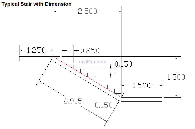
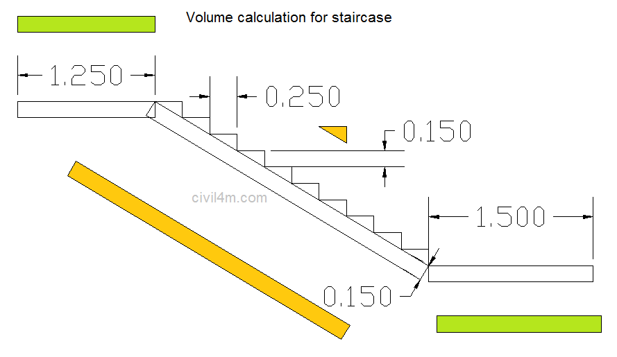
Below is one of the cross section drawn by me for illustration purpose (Staircase may or may not have such dimensions).

It shows typical 2 landings of 1.5 meter length (i included top landing 250mm portion in trade to make calculation simple)
It shows trade and riser dimensions and thickness of the slab.

From the above drawing we can calculate the height and length difference between two landings.
Sum of trades will give you the length which is 10 x 0.25 = 2.5 Meter
Sum of risers will give you difference between height, which is 10 x 0.15 = 1.5 meter.
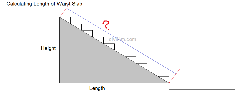
Waste slab is one which starts beneath the steps of stair, so we can calculate its length.


We can make use of Pythagorean theorem here to calculate the waste slab length
260px-Pythagorean.svg.png

(This image is property of wikipedia.org)

Waist slab 
5fd521cee81d583ce94bf6710984cc2a9eb7c3da


By this formula we get waist slab length as 2.915 meter.

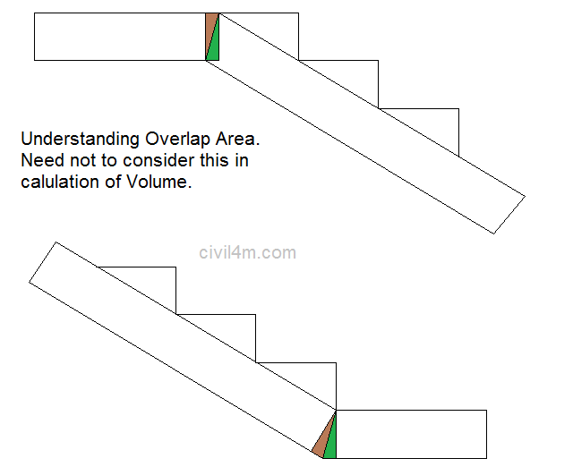
If we make this line as 150mm thick slab below, it wont connect to landing and we need to extend landing on one side and reduce on other side. the ration will be same and hence need not to worry for taking it into consideration for concrete quantity calculation.
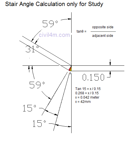
If start and end point of waist bottom slab not mention on drawing you can calculate it now, refer below image. 
If you take the vertical face all angles on right side goes add up to 180 degree and same on other hand.
You need to measure the angle from drawing.
and then using formula as shown in image you can calculate, how much bottom shutter to extend for matching the waist slab profile.

This two colored portion cancel each other on both side of landing as shown in below image (Do not worry will tell you how to calculate quantity)


After understanding this concept we can further move to calculating concrete volume in staircase, for calculation i am assuming width of landing and flight as 1.5 meter

The above image illustrate how you should calculate the volume.

1st or floor landing = 1.5 x 0.15 x 1.5 = 0.337 cum
2nd or mid landing = 1.25 x 0.15 x 1.5 = 0.281 cum
Waist Slab = 2.915 x 1.5 x 0.15 = 0.656 cum
Steps = 10 nos
area of triangle = 0.25 x 0.15 x 1/2 = 0.018 Sqm
Volume of steps = 10 nos x 0.018 x 1.5 = 0.281 cum

So total volume of staircase use for illustration becomes = 1.555 cum

This is how i do calculate volume of concrete, Your method may differ but the ultimate result will be same.

Now here we learn
How to calculate volume of staircase concrete
How to identify from where, waist slab shuttering to be started and where to end

Estimating and Tendering methods for Construction WorK


TRADITIONAL METHOD

  • The traditional structure for project procurement is where the employer takes his scheme to an advanced stage with his professional team before appointing a contractor.
  • The consultant’s role is seen as an independent one.
The designer is employed to advise the client and design the work

A quantity surveyor gives guidance on design costs and budgets,prepare bills of quantities, check tenders, prepare interim valuations and advises on the value of variations

  • A consultant structural engineers might be employed either by the client, or his advisers, to design the specialist parts of the project.
  • many major building owners and developers make use of in-house project managers to carry out all the design and financial control of the project.
Project management is therefore seen as a management tool and not a procurement method.

DESIGN AND BUILD METHOD

  • The design and build arrangement is an attractive option for clients. because the contractor accepts the responsibility for designing and constructing.
  • The benefits include: single-point responsibility, prices which reflect more closely the final cost to the leading to early completion.
  • The design and build arrangement is an attractive option for clients. because the contractor accepts the responsibility for designing and constructing.
  • The benefits include: single-point responsibility, prices which reflect more closely the final cost to the leading to early completion.
  • There is a contractual arrangement known as‘Turnkey’ this allows a client to procure from a single contractor all the requirements of a scheme in the shortest possible time.
the agreement will often include getting the land short-and long-term finance, fitting out , recruitment and training of personnel

DESIGN AND BUILD SYSTEM

  • A design and build contractor may commission design and cost services from outside consultants or can employ a design team from within their own organization.
  • At tender stage the employer will introduce some competition, either open or selective tendering, which is followed by clarification of the agreement and negotiation.
  • The number of contractors invited to submit tenders in the form of Contractor’s Proposals should be limited to three or four firms to reduce the high tendering costs.
  • A contractor might make a client’s brief fit his own preferred solution; the long-term life of a building might be overlooked and if the brief is vague, the client could pay an inflated price or take possession of an inferior building.
  • A client may not realize the importance of independent professional advice. The cost of abortive designs and tendering is a heavy burden on contractors’ overheads and eventually the costs will be passed on to clients.
  • The management contractor is appointed to work with the professional team, to con-tribute his construction expertise to the design and later to manage the specialist ‘package’ or ‘works’ contractors.
  • He is responsible for the smooth running of the work on site so that the contract can be finished within time and cost.
  • One development has been a combination of design and build and management contracting whereby the contractor produces a design and guaranteed maximum price, and the work is later assigned to a number of major package
  • A management contractor is selected using the following criteria:
  • Experience of management contracting.
  • Quality and experience of project staff.
  • Fee.
  • Programme and method statement.
  • The consultants, grouped under the title of ‘the professional team’, prepare the
  • drawings, specifications and bills of quantities for the various works contracts.
  • The Architect (or Contract Administrator) leads the Professional Team and issues
  • instructions to the management contractor on behalf of the employer.
  • The management contractor’s role is in coordinating the design and preparing cost studies at the pre-construction stage.
Clients are attracted to management contracting for the following reasons:

  • Construction can start before design is complete, and design can be changed during the construction phase;
  • Construction expertise is available to improve on the design;
  • Better coordination of specialist contractors through detailed planning of work packages and common facilities;
  • A contractor’s knowledge of construction costs is used to maintain tight budgetary control.
  • The specialists often carry the burden of late changes to drawings and specifications which are more common when design development takes place during construction.
  • The client cannot be sure of the final cost and will carry more risk. This is because the management contractor can pass on all the costs incurred for each trade, site staff and site facilities.
  • some clients would not want to deal directly with sub-contractors or be involved in every problem of time and cost that could arise.
  • At tender stage, each specialist contractor receives specifications, drawings, method statements, and details of the scope of works from which each estimator can prepare his own bills of quantity.
  • . All risks associated with the preparation of bills of quantity which must include all work needed to complete the package whether shown clearly on the drawing or not.
  • In some cases contractors must assess reinforcement quantities, for example, before the reinforcement is designed;
  • The need to complete elements of the design to the satisfaction of the architect;
  • Payment retention's may be kept for up to 12 months after the completion of the whole project;
  • Complex warranties for all contractors with design responsibilities.

Tuesday, October 2, 2018

Header bond


  • hearder bond or heading bond is the one in which all the bricks are laid as headers on the faces of walls .
  • width of the brick are thus along the direction of the wall
  • pattern is used only when the thickness of the wall is equal to one brick ( i.e 19 cm) 
  • overlap is usually kept equal to half the width of bricks 
  • This is achieved by using three - quarter brick bats in each alternate courses as quoins.
  • This bond does not have strength to transmit pressure in the direction of the length of the wall. As such it is unsuitable for load bearing walls 
  • It is useful for curved brick wark where the stretchers , if used would project beyond the face of the wall and would neccessitne inconvenient cutting 
  • It is also use din construction of footings 


BRICK MASONARY


1 . Stretcher : 
  • Stretcher is the longer face of the brick ( i.e. 19 cm × 9 cm )
  • A course of bricks in which all the bricks are laid as stretches on facing is known as a stretcher course or stretching course 
2. Header : 
  • Header is the shorter face of the brick ( i.e. 9 cm × 9 cm ) . A course of bricks in which all the bricks are laid as headers on the facing is known as header course or heading course . 
3. Lap : 
  • Lap is the horizontal distance between the vertical joints of successive bricks courses 
4 . Prepand : 
  • Perpend  is an imaginary vertical line which includes the vertical joint separating two adjoining brick 
5 . Bed : 
  • Bed is the lower surface ( 19 cm × 9 cm ) of the brick when laid flat 
6 . Closer :  closer may be of various types 
  • closer it is a portion of a bricks with the cut made longitudinally, and is used to close up bond at the end of course 
  • it helps in preventing the joints of successive sources ( higher or lower ) to cone iin a vertical line
6 . Queen - closer : 
  • Queen - closer it is a portion of bricks obtained by cutting A brick lengthwise into two portions .thus it is a brick which is half as wide as the full brick 
  • it also known as queen queen closer half 
  • if a queen closer is broken into two pieces , it is known aa queen closer quarter , such a closer is thus a brick piece which is one quarter of the brick size .
8 Bevelled close  : 
  • it is a special form of a king closer in which the whole length of the brick ( i .e . stretcher face ) is bevelled in such a way that half  width is maontmaint at one end and full width is maintained at the other 
9 . king closer : 
  • it is the portion of a brick which is such cut that widthof one its end is half that of a full brick while the width at the other end is equal to the full width 
  • it is obtained by cutting the triangular pices betwee  the center of one end and the centre of the other side 
  • it has half - header and half - stretcher face 
10 mitred closer : 
  • mitred closerit is a portion of a brick whoes one end is cut splayed or mitred for full width 
  • Angle of splay may very form 45° to 60° 
  • one longer face of the mitred closer is of full length of the brick while the other face is smaller in length
11 . Bat : 
  • it is the portion of the brick cut acress the width  
  • A bat is smaller in length then the full brick   
  • if length of the bat is equal to half the length of the original brick, it is known as half bat 
  • A three quarter - bat is the one having its length equal to three quarters of the length of a full brick 
  • if bat has its width bevelled . it is known is bevelled bat 
12. Arris : 
  •    it is the edge of a brick 

13 . bull Nose :

  • it is a special moulded bricks with one edge rounded or with two edge rounded 
  • these are used in copings or in such positions where rounded corners are perferred to sharp arises 

Monday, October 1, 2018

Rebound Hammer Test (Sachmidt hammer test )


  • It is a surface hardness tester for which an empirical correlation has been established between strength and rebound number
  • It is based on the principal that the rebound of elastic mass depends on the hardness of surface against which the mass impinges 
  • For this test, a rebound hammer also called Sachmidt hammer ,which weight about 1.8 kg and is suitable for both laboratory and field work 
  • Is has a spring controlled hummer mass that slids on plunger with in a tubular casing .
  • Hammer is forced against the surface of concrete bt the spring and the distance of rebound is measured on a scale which give indication of concrete strength 
  • This test is suitable for the concrete having strength in the range of 20-26 MPa 
  • Results are affected by facters sach as smoothness of surface size and shape of specimen , moisture condition of the concrete ,type of cement and coarse aggregate and extent of extent of carbonation of surface 

REQUIREMENTS GOVERNING REINFORCEMENT AND DETAILING

General :- Reinforcing steelof sametypeand grade shall be used as main reinforcement in a structural member. However.simultaneous use of...